Tuesday 27 September 2011

Creating a Surface


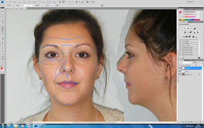
Having completed the slines I then made them into a surface by converting into an editable poly and in the edit geometry selected attach and attched all lines.
The topolgy is flat so to give it depth I used my other reference plate. Before this I needed to weld the mesh as the vertices were seperate.
By selecting the middle vertices only I straightned them using make planar tool X. Using the move tool I dragged the vertices on the X axis only.
I made the object see through by using key board short cut Alt X. I continued moving the vertices whilst trying not overlap then too much. Places such as the eye where unavoidable though.

This is how far I got today.

Monday 26 September 2011

Reference Setup and Using Splines to Model Head

Reference Plates

This involved creating two planes adding the topology picture to them via a bitmap. Using Bitmap fit to resize correctly and uvw-map gizmo to center. Setting the self-illumination to 100% so that the picture can be clearly seen at all angles. Then freezing the reference plates with 'in grey' setting unticked.
Modelling Process
To make to screen easier to work on I set up the viewports to be side by side in the configure - layout tab - viewport options and turned the grid off.
To start the modelling process I started by drawing lines and making them into splines over the top of the topology lines previously drawn. I ensured that the corner settings were set on the creation method and snap to vertex was on. When working on tighter areas such as round the eyes I lowered the pixel radiuos on the snap options.

As you can see in the picture above I followed the advice stated on the tutorial video of not putting in all the detail if it was not needed at this stage as it can easily be added later on. From previously working with 3DS max I know that the less amount of polygons are in a model the better the program will run.

Revised Topology


After reviewing my topology lines with Richard it was noted that they did not flow naturally across my face nor were they all four sided shapes. As stated before it is vital to have these aspects in the topology for 3dsmax to work correctly with them. Therefor I started again and managed to finally draw lines that would be acceptable.

Wednesday 21 September 2011

Completed Topology


Here is my completed topology. This was my second attempt from starting from scratch. I found it difficult to follow the key features on my face whilst keeping triangles and odd shapes to a minimum.

Monday 19 September 2011

Week 1 Reflection on Brief and first task

My initial reaction to the brief was that modelling my own face would be a difficult task and the final model would be unlikely to resemble me. However a good source of video tutorials have been provided that will guide me through the process in detail http://cg-india.com/tutorials/3dsmax_tutorials_organic_modeling.html.

The first step was to line up my front and side view photographs so that they can be used as references when modelling. By using the lens distortion tool in photoshop and rulers as guides I flattened out my face and lined them up exactly. I had to take a second set of photographs as the first ones were too different to get a good match.

After this I was able to start on my topology of my face by drawing lines. I did this by defining my basic features then building quads whilst trying not to draw triangles as these cause problems in 3DS Max.

I hope to have this stage finished by next week.

I am looking forward to the group project as I will have the opportunity to use more of my own creative initiative when planning. We decided to research Finchingfield Guildhall individually and meet before next lecture to discuss our findings.