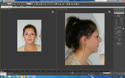
Reference Plates
This involved creating two planes adding the topology picture to them via a bitmap. Using Bitmap fit to resize correctly and uvw-map gizmo to center. Setting the self-illumination to 100% so that the picture can be clearly seen at all angles. Then freezing the reference plates with 'in grey' setting unticked.
Modelling Process
To make to screen easier to work on I set up the viewports to be side by side in the configure - layout tab - viewport options and turned the grid off.
To start the modelling process I started by drawing lines and making them into splines over the top of the topology lines previously drawn. I ensured that the corner settings were set on the creation method and snap to vertex was on. When working on tighter areas such as round the eyes I lowered the pixel radiuos on the snap options.

As you can see in the picture above I followed the advice stated on the tutorial video of not putting in all the detail if it was not needed at this stage as it can easily be added later on. From previously working with 3DS max I know that the less amount of polygons are in a model the better the program will run.
No comments:
Post a Comment